Your cart is currently empty!

Custom Fonts for Dice in TinkerCad
I found interest in dice making dice this month and wanted to share what I’ve learned using TinkerCad. Assuming you’ve completed the TinkerCad tutorials, this post will only share how to take existing objects ( dice ) and add custom numbers and how I made my preferred number adjustments.
The shape of the dice can be found by searching for public designs or just copying my sharp edge dice design. The numbers were originally individual image files that were then converted to SVG file format. Here’s how I applied custom fonts:
Let’s get started
Using the number 8 as an example, I used Google Fonts to view my preferred font design in the largest font size available. Explanation for the large font size coming up:

I used Photoshop but thought instructions using a screenshot to capture the number as an image file would work for most – this is why a large font size is recommended. You can then take screenshot of the Google Fonts page using the instructions from https://snag.gy/ to capture number in the style you prefer, then save the cropped number to the computer. Do this for every single number or image:

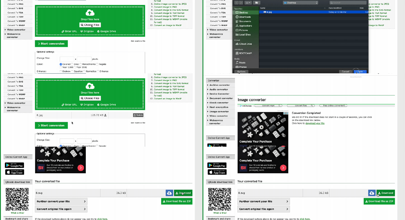
The next step will be to convert the images ( number ) into a format that TinkerCad can read as a 3D object. If you’re not comfortable converting the file in Adobe Illustrator, you can use Online-Convert.com’s SVG image converter:

You should have an SVG file for each of the numbers by now. Next, you’ll have to Import the SVG files to the Workplane then add the item/number your Part Collection. Both of these steps can be done in the right sidebar in TinkerCad:
Import the SVG for a number and resize it:

Add the object to your Part Collection to use the object for the sides of other dice:

Now, it’s time to add your number to the side of a die. It was easiest to work with an object when it’s centered on the Workplane. Using the recommendation from this post, I used the ruler tool to center another object and use it to align the piece I was working on to the center:

With one side ready, move your Workplane to that side and drag your object to it. This is where you can set the angle, depth and thickness of the number. The thickness is not important and ignored after the object has been converted into a hole – the number will have to be set to “hole” so the depth will be applied when it’s grouped with the side. Here I set Snap Grid to .5mm, the size to 9mm:

I then centered the object to the side I was working on:

Turned the objects angle to match my preferred angle:

Changed the thickness to 2mm ( not important and any number greater than 1mm will do ), the depth to -0.5mm, and finally make the object a hole before grouping it all together:

After making the object a hole, and setting its size, angle, and depth, you can now group it with all other numbers and sides to see the completed side:

It took me a bit to get used to the snap grid reverting each time the page loaded and I was not as quick in my first few hours as I am now. You may not be either but like all things, you’ll get better with practice. 😃
Printing custom dice
Once all dice are done, you can highlight each object to save individual objects per file or highlight all objects and export the objects as one file:

Now, you can use these instructions to make your own custom dice or download the compressed STL file from my TinkerCad design and have your dice printed at Shapeways for around $70 US.

Here is how they turned out compared to a Chessex set, up polished, and a coffee stain:

Side View

I think the sightly large size allows for more flexibility to showcase some mad resin skills!
Dice size chart for my sharp ass dice:
- D8 – 28mm (from tip to tip)
- D6 – 16mm
- D10/D% – 28mm (from tip to tip vertical)
- D12 -19mm
- D4 20mm
- D20 -21mm
Resizing them will take some knowhow with TinkerCad as you’ll have to tilt the dice measured from tip-to-tip from their flat surfaces. Either way, I hope this write up was a help.